Summary
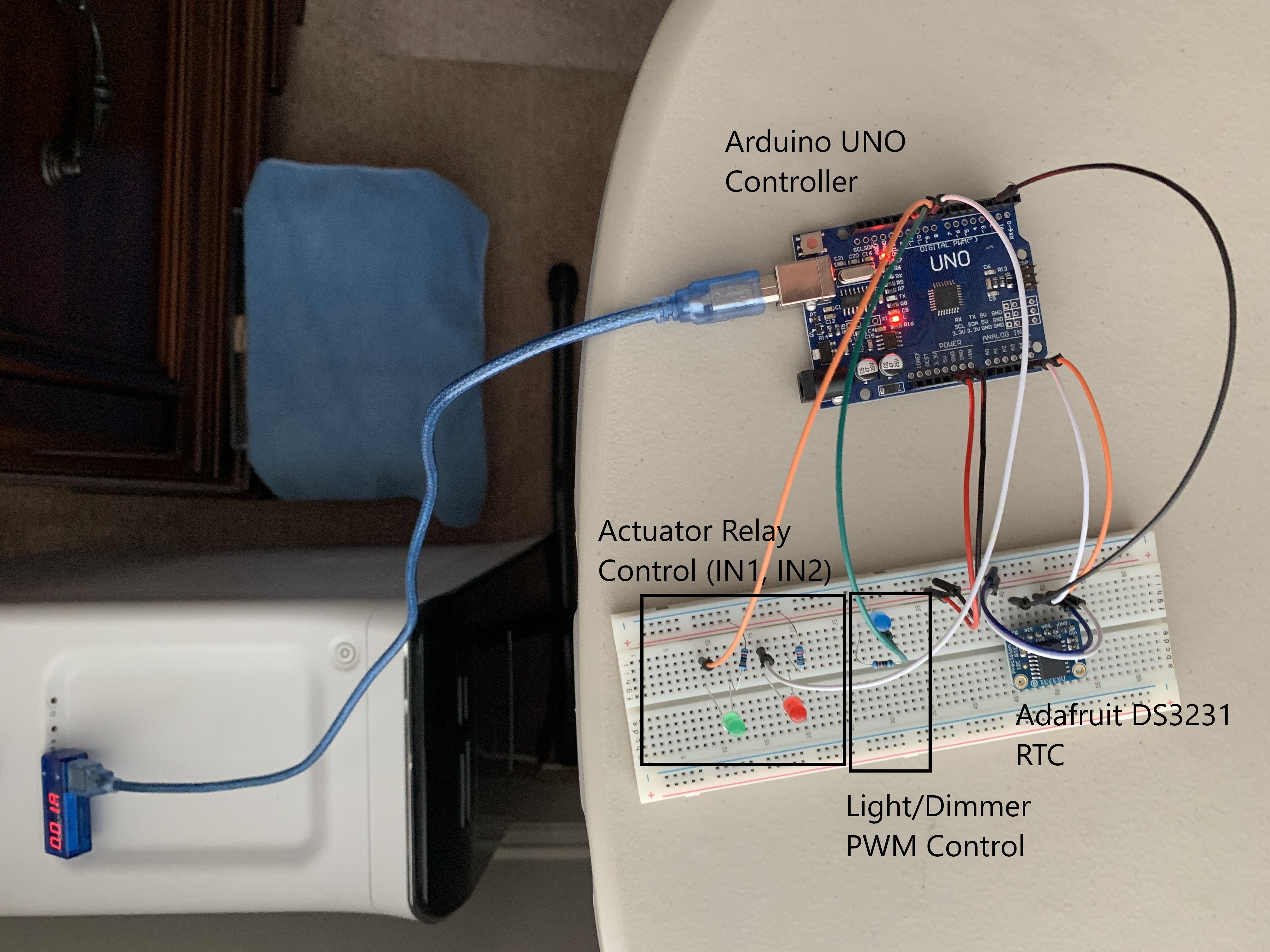
The client had purchased several components to build a controller for a chicken coop. This included an Ardunio UNO, Adafruit DS3231 precision real-time clock (RTC), Pololu 5V 1A regulator, 2-channel relay module, AC light dimmer (forward phase) module, 12V linear actuator, and a 12V battery. The Ardunio sketch was to
- At sunrise retract the linear actuator for 3 minutes.
- 1-hour after sunrise turn on lights at 100% brightness
- Leave lights at 100% brightness for 12.5 hours, then gradually dim over a 1-hour period.
- At sunset extent the linear actuator for 3 minutes.
Implementation
The system wiring was straight forward. For the actuator relay control the JDVcc was not connected to Vcc. JDVcc was connected to the 5V voltage regulator.
Key to the design was the RTC. The implementation uses both alarms 1 and 2 with the interrupt pin for timing events. The timing events were:
- Sunrise
- Actuator time on
- Sunrise + 1 hour
- 12.5 hours light period
- Light dimming period
- Sunset
Sunrise and sunset times were provided by the Dusk2Dawn library and are calculated based on lat/lon and UTC offset. All times were kept in standard time. To set the RTC date and time a helper sketch was provided. This minimized the programming of a user interface into the controller that would only be used once.
The sketch used two state machines to manage events. One state machine managed actuator control and the second manage light control. The basic operation would set the next time alarm and then wait in the next state for the alarm to occur. When the alarm occurred the action was taken for the state and the next alarm/state was set. Moving being states occurred only when an alarm occurred. The RTC alarm signal was polled instead of using an interrupt since the I2C interface also required interrupts reducing the interrupt handler to setting flags that were then polled in the main body of the code.
Light dimming used PWM control. The Arduino PWM is 8-bits allowing 256 steps. A simple division was used to calculate the time between step, which turns out to be 14 seconds between dimming steps for a 1-hour period. This dimmed the lights over a 59 minutes and 44 second period (not the full 1-hour as requested by the client). A future enhancement would to adjust the steps and whole seconds to fill a 60 minute period.
The sketch used multiple defines that allowed the client to change parameters if necessary.
define LIGHTONTIME 750   // lights on time in minutes
define DIMTIME 60        // time to dim in minutes
define RETRACTTIME 3     // actuator retract time in minutes
define EXTENDTIME 3      // actuator extend time in minutes
define LAT 38.47136      // lat for sunrise/set
define LNG -77.95664     // lon for sunrise/set
define UTC -5            // utc offset for sunrise/set
A breadboard environment was setup to test the sketch. LEDs were used to simulate the connections to the relay controller and AC light dimmer. Text was also set to the serial port (usb) for additional feedback.
The sketch was developed in the Arduino IDE environment 1.8.12 and used the ds3231FS by Petre Rodan and Dusk2Dawn by DM Kishi libraries. The ds3231FS library was selected over the Adafruit ds3231 library for the alarm control interface.
Issues
There were two minor issues during development and both were related to the RTC. First is to remember to always read the datasheet. Alarms on the RTC work incrementally, i.e. if you want an alarm based on the hour you must also enable seconds (alarm 1 only) and minutes.
The second issues is the RTC control register is not readable, so when enabling/disabling an alarm you don’t know the state of the second alarm. So an internal shadow register was implemented in the sketch to maintain the state of the control register prior to writing.